With the advent of enticing user experience, Electrification and ADAS features in the car, vehicle architecture is strongly headed towards Domain Controllers. In this article, let us discuss the following aspects:
- What is a Domain controller? Why are OEMs going towards Domain Controllers?
- What considerations should we have for functional safety in Domain Controllers?
- In case multiple suppliers are involved in the development of the Domain controller, what challenges exist and how to handle them?
What is a Domain controller? Why are OEMs going towards Domain Controllers?
Traditional vehicle architectures are de-centralized and distributed with one ECU typically implementing 1 feature/function. Every time a new function/feature is added, a new ECU is added. This kind of an architecture is extremely complex and heavy in terms of wiring (lots of cables, contacts, fusing, relays etc) and makes it very expensive to package all the ECUs into a car. Also, with the increased focus on automated driving and User experience, the car is becoming more software centric. There is a need to introduce additional apps or new features/functions with SW over-the-air updates without having to add or change hardware. This has driven OEMs towards a centralized vehicle architecture, where several ECUs related to a single domain are combined into a single ECU. Such an architecture is significantly lighter and simplified in terms of production logistics processes and has an improved quality. An ECU that consolidates several functions of a domain is called a Domain Controller.
Here is a view of a de-centralized traditional vehicle architecture. Each box in this picture represents an ECU.
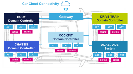
Here is a view of the centralized Domain-controller based vehicle architecture.
There are Domain Controllers for different domains:
A DC implements all the functions within a single
System-on-chip that has multiple cores with the required real-time as well as computing power capabilities.
Research predicts that overall domain controller penetration will approach 60% by 2028, though there is no concerted effort towards domain-based architectures.
From an ISO26262 perspective, a Domain controller can be considered to implement several “Items” or parts of several “items”. For e.g., an ADAS DC implements different ADAS functions such as ACC, AEB etc could be considered as being a part of the ACC Item, AEB Item and so on.
What considerations should we have for functional safety in Domain Controllers?
1. Readiness of DC Architecture for the highest ASIL level requirement
A Domain Controller is not fixated in terms of features/functions and is bound to feature upgrades, additions, and modifications during its lifetime. From a Functional Safety point of view, the OEM/Tier 1 should be able to “forecast” the highest ASIL level required from the DC. Forecasting must be done based on what new features might get added and what will be the ASIL level required for them. The DC’s SW and HW Architecture should be designed to achieve this highest ASIL level requirement.
For example, let us take a cockpit domain controller which currently has ASIL-A Safety goals. It has an ASIL-A qualified SoC and a SW Architecture that has an ASIL-A Operating System and 2 Partitions for ASIL-A and QM.
Now, if this DC gets ASIL-B Safety goals in future, its existing architecture will not be able to support it. It will be required to replace the SoC and OS to an ASIL-B qualified one and to create an additional partition for ASIL-B. The DC’s HW design may also have to be modified to achieve the required HW metrics.
The Architecture of this Cockpit DC in the above example was not scalable to support the newer Safety goals at higher ASIL levels. This flaw in forecasting is exactly what must be avoided.
Let us take another example of an ADAS Domain controller that currently supports an ASIL-C Architecture and has a camera sensor at ASIL-C. If this DC must support ASIL-D Safety goals in future, its existing HW architecture does not support it. In this case, the DC must either 1) upgrade to a camera sensor at ASIL-D or 2) perform an ASIL decomposition between the Camera and another redundant sensor that is at least at ASIL-A, for which there must be an additional sensor considered in the DC’s Architecture.
2. Existing Safety features not affected by SW Upgrades
When SW Upgrades are performed on road, this should not affect the other Safety features that are already qualified, else a re-qualification will be required every time for even the features that did not have any changes, making it an extremely costly affair.
3. Achieving fail-safe, fail-degraded and fail-operational requirements of several features
The principles of achieving fail-safe, fail-degraded and fail-operational requirements are the same whether it is a traditional ECU or a DC. However, what makes it interesting for a DC is the fact that there are several Safety features that co-exist together with a wide variety of fail-safe, fail-degraded and fail-operational requirements. It is intriguing to achieve all of it together in a single system.
A fault in 1 function should not affect another function unless they are related to one another. Otherwise, it would lead to a total loss of availability of all functions. For e.g., in an Instrument Cluster-Audio Domain DC, if the Audio system failed, the Instrument cluster should still be able to function and provide the required safety notifications and indications to the driver. In an ADAS system, if a lane keep assist function fails, it should not affect the performance of the Automatic Emergency braking function.
The System Architecture of the DC should identify the faults that will affect each function and to move the function to a fail-safe/fail-degraded state only if those associated faults happen, and not for any other faults that won’t affect the function. For example, if an Emergency braking function uses Radar sensors and a park assist uses ultrasonic sensors, a failure of the ultrasonic sensors should only degrade the park assist feature. The Emergency braking function should still be fully available.
If there is a common fault that cut across functions and affects all of them, such as a CPU failure, this would lead to an overall fail-safe condition for all functions.
Fail-operational requirements can usually be achieved only by implementing HW redundancy. For e.g., the DC can have 2 independent SoCs performing the same processing such that even if 1 fails, the other SoC continues to provide the functions. End-to-End redundancy of the feature must be considered to achieve fail operational behavior. If the feature reads some inputs from a sensor, a redundant sensor can be implemented in the design as a backup in case of the primary sensor failure. Two independent CAN channels to receive and send the same messages and redundant actuators are additional aspects that a DC having fail-operational features must consider.
In case multiple suppliers are involved in the development of the Domain controller, what challenges exist and how to handle them?
It is quite common to have different suppliers develop different functions of a DC. This is due to various reasons. One aspect is the sheer complexity of the System and the development effort required for a single supplier to develop the entire system. The bigger challenge is the knowledge/technical expertise required to develop every function. A single supplier may lack the knowledge and expertise to develop all the functions.
The challenges when dealing with suppliers are quite similar, whether it is a DC or traditional ECU. However, the reason we highlight it here is because a DC typically has many more suppliers. It makes it obviously much more challenging to get the required Safety case from each supplier and to bring them all together to deliver the safety case of the overall system.
The Tier 1 is typically the overall responsible of the Safety concept. The Tier 1 must know what is required from each supplier to gain confidence that risks have been sufficiently mitigated in the System.
The typical challenges when dealing with suppliers are:
1. The responsibility of the Supplier is vaguely defined.
E.g.,1: let us say that a Supplier provides a complex IC for the DC, such as a Micro or a sensor. Should this supplier provide only the HW? Or does the Tier 1 need any supporting SW as well from them?
E.g.,2: if Supplier 1 develops function 1 and Supplier 2 develops function 2, who is responsible to ensure FFI for function1 from function2? Is it the responsibility of Supplier1 or Supplier 2 or anyone else?
2. The ASIL level of the HW/SW provided by the Supplier is assumed.
E.g., Supplier says that their HW/SW supports up to ASIL-B or says they have a “roadmap” for ASIL certification, but Tier 1 assumes that the HW/SW is developed according to ASIL-B
3. The Timeline by which the Supplier provides the required ASIL SW/HW does not meet the Project deadlines.
This is a common problem not only for Safety but even otherwise. In case of Safety, what often happens is that a HW/SW is functionally ready on-time, but the Safety case completion is delayed. Hence, the Safety case of the Supplier is not completed before the project’s deadlines.
Uncertainties in Supplier responsibilities arise because of the lack of a clear definition of every supplier’s role and responsibility in the DIA. Supplier DIAs are often blindly reused from previous programs without completely considering the challenges and the context of the current program that is developed. This must be certainly avoided. Supplier DIAs must be evaluated right at the RFQ stage if possible. All the real time challenges in implementing the Safety concept must be thought about upfront. Instead of doing a post-mortem after things go wrong, it is better to do a pre-mortem at start of program on what should be considered right at start to prevent a failure down the line.
Summary
Domain Controllers seems to rule the roost for the next decade. However, a drawback with the DCs is that many Domains may physically span the entire vehicle. Hence, Automakers are also investing in zonal architectures. A Zonal architecture addresses domain architecture shortcomings by combining ECUs that are physically close under a single zonal controller. This gives the benefit of reduced wiring and weight — at the cost of increased software complexity. This is because the zonal controller must be able has to differentiate traffic between the ECUs that connect to it according to function.
We will leave you with this picture that provides a simplified view of the different architectures.
Sources for more interesting reads:


Comments
Post a Comment